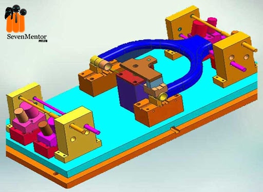
Introduction to JIGS AND FIXTURES(PART-B) –
GENERAL RULES FOR DESIGNING –
- Production of the cost will compare with the work in a present tool with the expected production of cost, using the tool it will be made and see that the cost of buildings is not excess of expected gain.
- We can decide upon locating points and clamping of outline arrangement.
- Make all clamping and binding devices as quick acting as possible.
- Make the jig fool proof.
- Make some locating points adjustable.
- Avoid complicated clamping arrangements.
- Round all corners.
- Provide handles wherever these will make handling easy.
- Provide abundant clearance.
- Provide holes on escapes for chips.
- Locating clamps will be in the best location to resist the pressure of the cutting tool at the work time.
- Place all the clamps as near as possible to opposite some bearing points of the work to avoid action springing.
Test all jigs as soon as made, its Before using in the shop.
For Free, Demo classes Call: 8149467521
Registration Link: Click Here!
MATERIALS USED –
Jigs & fixtures are made up of different types of materials, some materials will be hardened to resist wear.
Materials generally used –
High-speed steel –
Cutting tools : like drills, reamers & milling cutters.
Die steels –
Used for press tools, contain 1% carbon, 0.5 to 1% tungsten and less quantity of silicon and manganese.
Carbon steels –
Used for standard cutting tools.
Collet steels –
Spring steels containing 1% carbon, 0.5% manganese and less of silicon.
Non-shrinking tool steels –
- High carbon or high chromium.
- Very little distortion heat treatment.
- Used widely for fine, intricate press tools.
Nickel chrome steels –
Used for gears.
High tensile steels –
Used for fasteners like high tensile screws.
Mild steel –
- Used in most part of jigs and fixtures
- Cheapest material
- Contains less than 0.3% carbon.
Cast iron –
Material are used for any odd shapes to some machining work as well as laborious fabrication –
- CL usage requires a pattern for casting.
- Its contains more than 2 % of carbon.
- It has self-lubricating properties
- It can withstand vibrations and is suitable for the base.
Nylon material and fiber –
This material are used for soft lining for clamps to damage to work pieces due to clamping pressure. Read more at AutoCAD Classes in Pune
Phosphors bronze –
Used for Nuts & high tensile strength as well as used for nuts of the lead screw.
FACTORS TO BE CONSIDERED FOR DESIGN OF JIGS AND FIXTURES –
Component-
Design to be studied carefully be submit do confirm that work is performed in a proper way or sequencecly and need to try it for maximum operations should be performed on single setting in machine setting.
For Free, Demo classes Call: 8149467521
Registration Link: Click Here!
The capacity of the machine-
Careful considerations to be performed on type and capacity of machine.
Production requirements –
Design should be made on basis of actual production quantity of requirements.
Location –
- Location should ensure equal distribution of forces throughout all sequence of operations.
- Location should be hard resistant and high degree of accuracy.
- Movement of work piece should be restricted.
- Should be fool proofed to avoid improper locations of the work piece.
- Should facilitate easy and quick loading of work piece.
- Redundant locators should avoided.
- Sharp corners must avoided.
- At least one datum surface should established.
Loading and Unloading Arrangements –
- There should be adequate clearance for loading and unloading. Hence process becomes quick and easy.
- Size variation must accepted.
- It should be hardened material and non-sticky.
- Clamping arrangements.
- Quick acting clamps must use as far as possible.
- The clamping should not cause any deformation to the work piece.
- It should arranged directly above the points for supporting the work.
- Power driven clamps are favored as they are quick acting, controllable, reliable and operated without causing any fatigue to the operations.
Features of clamps –
- Clamping pressure should be low
- Should not cause distortion
- Simple and fool proof.
- Movement of clamp should be minimum.
- Case hardened to prevent wear.
- Sufficiently robust to avoid bending.
Clearance between Jig and Component –
- To accommodate various sizes if work.
- Chips or Burs to pass out through the opening between them.
Ejectors –
- To remove work from closing fitting locators.
- Speeds up the unloading as well as loading of the product from the tool and hence production rate.
For Free, Demo classes Call: 8149467521
Registration Link: Click Here!
Base and body construction –
Methods are used –
Machining, forging and machining, casting Fabricating, welding.
Tool guiding and cutter setting –
Using a cutter-setting block, the cutter is set its relative towords the work in the fixture. The drill bush are fitted to jig plates for guiding the tools.
Rigidity and vibration –
Must possess enough rigidity and robustness. AutoCAD Training in Pune need to take care the work piece cause its should not vibrate as it may lead to unwanted movement of work piece and tools.
Safety –
Operations should be assured full on safety.
Cost –
Should be simple as possible & Cost incurred should be optimum.
Materials is generally used –
| Sr. No | Part Name | Material |
| 1 | Jig body | Cl |
| 2 | Stud | MS |
| 3 | Drill/Bush | Gun metal |
| 4 | Pin | MS |
| 5 | Nut | MS |
CATIA & SOLID WORK SOFTWARE ARE USE FOR CREATING JIG & FIXTURE. Learn more at AutoCAD Course in Pune.
Author:-
| SevenMentor Pvt Ltd.
© Copyright 2021 | Sevenmentor Pvt Ltd.

